REVIEW | ROBOT CALIBRATION
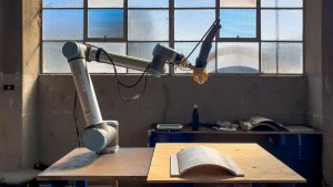
Robotic arms are a series of joints linked together in a kinematic chain
Calibration is critical in the field of robotics as it allows for enhancement of a robot’s accuracy through software rather than changing mechanical components. This article will go over some basic concepts involved in end effector calibration otherwise known as adding a new tool centre point on a robotic arm. Most industrial manipulators have six degrees of freedom or six joints (see Figures 1 & 2). The starting link always begins where the robot is physically mounted. These joints can be described as having a parent-child relationship. The hierarchy of these joints is important as the child joint is always defined in reference to, and therefore dependent on, the parent joint. The last link on the kinematic chain is typically referred to as the end effector which has a tool centre point (TCP). It is this TCP point that the user will manipulate in 3D-space, if in cartesian control. To make robotic arms useful, various end effectors (i.e. grippers, 3D sensors, rotating tools) can be attached in order to complete various operations. As a result, defining a new TCP is necessary to utilise the mounted tools.
Figure 1: Simple drawing of a robotic arm and joints
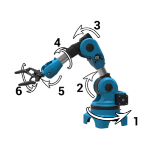
Figure 2: Example of joints on an industrial robotic arm
There are several ways to add a new TCP point on a robotic arm and most robotic arm manufacturers will
provide their own methodology. Ultimately, all these methods involve measuring the pose of your new end
effector in 3D-space, with respect to the last joint of the manipulator. The key feature to make note of
when adding a new TCP, is the parent joint’s coordinate frame (see Figure 3).
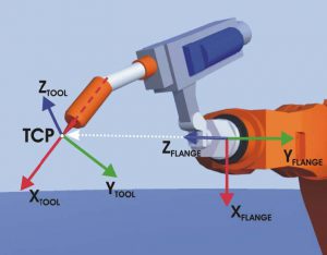
Figure 3: Example of TCP point being defined from the last flange joint on a KUKA
To define a new TCP, the position and orientation is required to make up the pose. The position aspect can
be gathered from physically measuring it out. It’s important to know the coordinate frame as this determines
whether elements are positive or negative, and which axis to measure along. Depending on the complexity of
the end effector, it can be quite difficult to measure the TCP point. If there is an accurate 3D model, the
position information can be gathered from this, but ultimately the accuracy in robotic arm control is
dependent on how close the most is representative in real life.
The orientation is crucial for cartesian control. The controller is given target poses and it is ultimately
trying to match the robot’s end-effector coordinate frame to the target’s. If the orientation of the TCP is
ill-defined, it can cause large sweeping motions. There are four key things to remember when defining a new
orientation:
- Orientations are simply defining a new XYZ coordinate frame (see Figure 4A)
- All XYZ coordinate frames have to abide by a right-hand rule to be valid (see Figure 4B – this rule defines the order XYZ axes can exist, thumb is X, pointer is Y and middle is Z axis) and follow conventions to determine positive rotation (figure 4C)
- The order of rotations also impacts the ending result of a coordinate frame.
- All orientations, while maybe named or ordered differently, will be defined using either euler angles (x,y,z) or quaternions (x, y, z, w) with the units being either in degrees or radian.
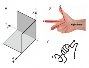
Figure 4A: (A) A 3D coordinate frame in cartesian space. (B) The right-hand rule all frames will abide by. (C) The thumb represents the axis, and the curled fingers represent convention for positive rotation.
Figure 4B: Example of orientations defined in KUKA manipulators. ABC angles represent ZYX coordinate frames (note, reversed and named differently from conventional frames).
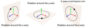
Figure 5: Coordinate frame showing the separated axis rotations
This article touched on the basic concepts involved in calibrating a new end effector on any kind of robotic arm. It is important to have an understanding of the underlying theory that underpins how robotic arms are structured, but the best resource to understand your robotic arm will be the manufacturer’s manual.
The Future of Manufacturing
With support from the Innovative Manufacturing Cooperative Research Centre (IMCRC), Design Robotics is collaborating to present a range of new
fabrication and vision systems solutions. The goal is simple – to design for human intelligence and optimize
the relationship between people and machines.
Pushing the limits of industrial robotics is a move to empower people. Navigating the increasing complexity
of manufacturing inevitably supports human experience and enhances skills acquisition. At its heart, this
approach celebrates the best of what robots and machines can achieve – problem-solving, and the best of what
humans can do – social intelligence and contextual understanding.